

Illustrated techniques for transapical aortic valve implantation
Introduction
Within the last decade, transcatheter aortic valve replacement (TAVR) has come from relative obscurity to become a procedure that is practiced at most major health centres worldwide and the technical details of this procedure have been described by many (1-4). The rapid adoption of TAVR in medical practice makes it one of the fastest therapeutic modalities incorporated and evaluated by randomized control trial (5). Transfemoral (TF-TAVR) retrograde and transapical (TA-TAVR) antegrade approaches were the most widely practiced. TA-TAVR is the preferred procedure where the peripheral access is limited due to size, calcification and torturosity. TA-TAVR provides a more stable platform for TAVR, due to the more direct and shorter distance to the native aortic valve. Access via the subcalvian artery and ascending aorta are emerging to be viable alternatives. Procedural technique can be very important in high-risk patients and remains among the few modifiable factors. Therefore, it is worthwhile to describe the intricacies of the TA-TAVR approach, with the aid of photographs. The technique described is intended for transapical implantation of the SAPIEN transcatheter valve using the Ascendra delivery system (Edwards LifeSciences, Irvine, CA, USA).
Successful TA-TAVR is discussed in eight sequential steps: (I) Patient selection; (II) Preparation; (III) Imaging; (IV) Surgical access; (V) Balloon valvuloplasty (BAV); (VI) Positioning; (VII) Deployment; and (VIII) Surgical closure.
Preoperative management
Patient selection
Patient selection is the single most important step that can determine success or failure of TA-TAVR. It will be discussed in depth by other authors in this special issue.
Preparation
The patient is placed in the supine position and elevation of the left chest is not routinely required. All electrical cardiogram leads and defibrillator pads are placed appropriately but out of the way of the anticipated fluoroscopy sites and allow access to the sternum and left thorax. Lines for continuous arterial blood pressure monitoring and oximetry are placed before the patient goes under a general anaesthetic and is intubated. TA-TAVR can be performed without general anaesthesia, however, very limited experience has been reported at the present time (6).
Early in the development of the procedure, the left lung was collapsed to allow for better visualization of the left ventricular apex. However, it has subsequently been found that the left lung rarely interferes with exposure of the ventricular apex. Lung isolation is no longer required. Pulmonary arterial catheter for continuous cardiac output monitoring is reserved for patients with poor ventricular function.
For precautionary reasons, an important part of the preparation process is the presence of perfusionist and a primed cardiopulmonary bypass circuit, in the event of hemodynamic instability and surgical misadventures.
Operative techniques
Imaging
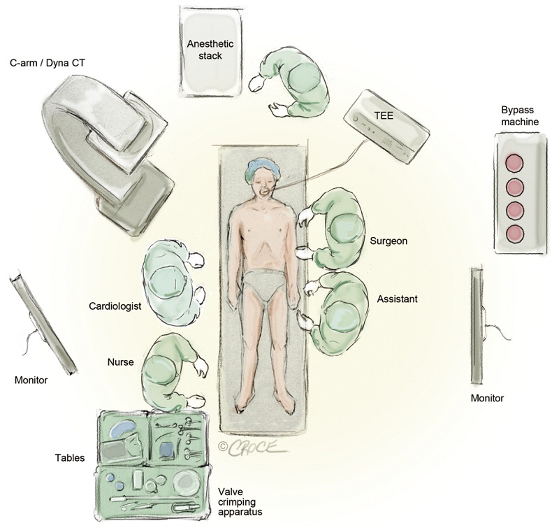
In our initial experience, TA-TAVR was performed in the operating room using a portable C-arm fluoroscope. However, the image quality was found to be rather poor to the point where it was difficult to visualize the aortic valve. A greater quantity of dye injection at the aortic root was used to better define the native aortic valve (AV) and this was of some concern as a large dye load can be hazardous in patients with compromised renal function. Moreover, poor visualization can be a major causative factor for valve malpositioning, paravalvular regurgitation and embolization. With this in mind, it is strongly advised that TA-TAVI should only be undertaken in a hybrid operating room or catheterization laboratory with high-definition fluoroscopic equipments and multiple monitors. Figure 1 demonstrates the layout of our hybrid theatre. As well, it is imperative that transesophageal echocardiography (TEE) or intracardiac echocardiography (ICE) be available to access ventricular, valvular functions and the annular size. In addition, TEE is an invaluable tool to help with the positioning of transcatheter valve stent prior to its deployment.
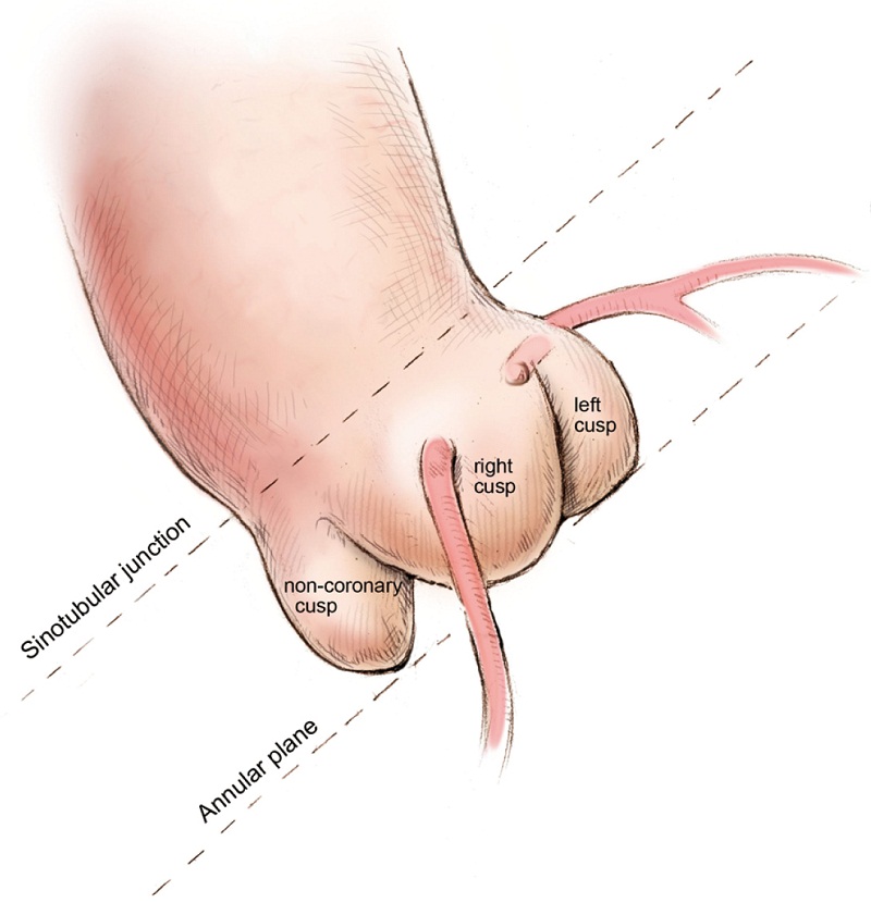
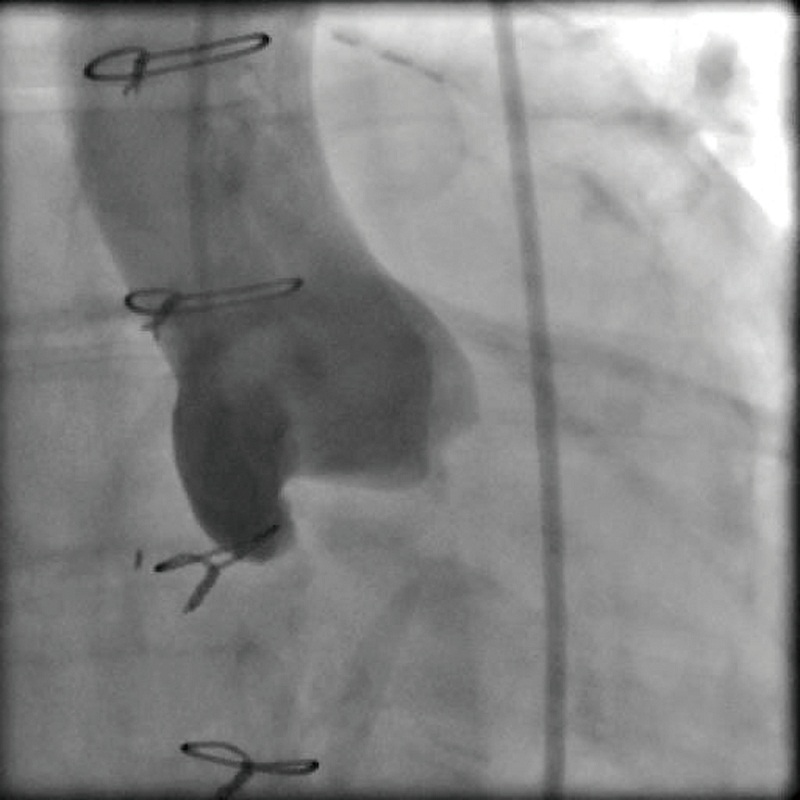
Defining the implant angle, where the bases of all three aortic cusps reside on the same plane is crucial to a successful implant (Figure 2). An initial root aortogram performed with a 7 French (F) pigtail catheter at the base of the non-coronary cusp at an angle of AP and caudal 10o should guide the operator to define the optimal line of perpendicularity (Figure 3). Several imaging software systems, such as DynaCT (Siemens AG, Erlangen, Germany), Innova HeartVision System (GE Healthcare, Chalfont St Giles, UK) and C-THV (Paieon Inc, Park Afek, Israel) utilize 3-D rotational angiography to better define the aortic root anatomy and identify the line of perpendicularity. Preoperative multi-slice computer tomography (MSCT) can provide valuable information on annular size and implant angle.
Surgical access
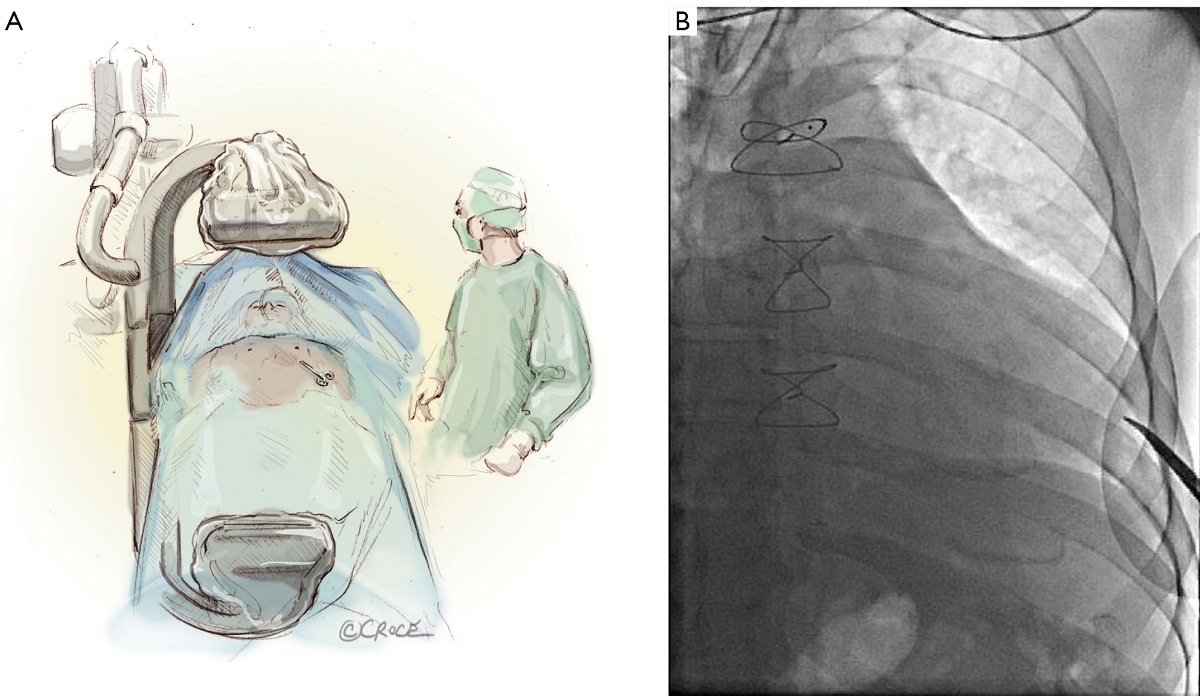
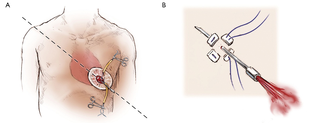
The left ventricular apex is located by placing the tip of a hemostat on the patient at the apex location as seen on fluoroscopy (Figure 4A, B). This method has been found to be reproducible and more useful than palpation for the apex beat, particularly in patients of high body mass index. Preoperative CT guided or intra-operative surface echocardiography is used by some groups. Sixth intercostal space (ICS) is the most common access site, followed by 5th ICS. Over the previously determined location of the apex, a 3 cm incision is made. The incision is made over the top of the rib to avoid trauma to the neurovascular bundle. When it is possible, using the lower ICS is more convenient in terms of a straighter trajectory to the aortic valve. The left lung, as previously mentioned, does not usually interfere with the exposure of the left ventricular apex. A soft tissue retractor, Alexis Retractor (Applied Medical Corp., Rancho Santa Margarita, CA, USA) is inserted into the incision to retract the soft tissue without spreading the ribs. This method greatly reduces post-operative pain (Figure 5).
The pericardium is then incised and opened near the left ventricular apex and pericardial retraction sutures may aid further exposure. In cases where the patient has a history of previous cardiac surgery, dissection of pericardial adhesions is avoided.
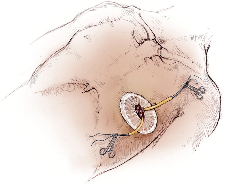
As with all procedure, transapical TAVR has an Achilles heel and that is haemostatic control of the left ventricular apex. Particular care must be taken when placing two large pledgeted orthogonal mattress sutures using 3-0 MH polypropylene sutures (Ethicon, Somerville, NJ, USA) to obtain full thickness of the left ventricular wall. Each of the two mattress sutures are snared and passed through tourniquets that can be tensioned at the time of sheath removal (Figure 6). The sutures are appropriately placed to allow space for the largest sheath, initially an Ascendra sheath (Edwards LifeSciences, Irvine, CA, USA) with an internal diameter (ID) of 33 F sheath and more recently a smaller (24 F ID) Ascendra II Plus delivery system. The true apex should be avoided, as it is frequently thin and covered by adipose tissue. A ‘bare spot’ lateral and cranial to the true apex should be used to avoid catastrophic ventricular rupture.
Rapid ventricular pacing is required for the implantation of balloon-expandable prosthesis, in order to decrease forward flow during the valvuloplasty and valve deployment. One unipolar epicardial pacing wire is placed directly onto the left ventricle and another on patient’s chest wall. Alternatively, transvenous pacing lead can be implanted into the right ventricle. Pacing rate of 140 to 200 beat per minute frequently results in 1:1 ventricular capture and lowers the pulse pressure and forward flow. The rapid pacing periods and episodes must be minimized to ensure hemodynamic stability, especially in patients with depressed left ventricular function and/or non-revascularized coronary artery disease.
Hemostasis of the apex is ensured prior to the administration of unfractionated heparin to achieve an activated clotting time of greater 250 seconds. A 14-gauge Seldinger needle is positioned in the centre of the mattress sutures’ square and advanced to enter the chamber of the left ventricle. The angle of entry should be pointing toward the right shoulder, whereby crossing of the native aortic valve can be easily achieved. Correct placement can be confirmed by the visualization of bright red blood spurting with each ventricular contraction (Figure 7). If oxygenated blood does not spurt despite advancement of the needle, this suggests the needle may be in the interventricular septum. Also, the needle could be inadvertently embedded into the hypertrophied ventricular wall if the angle of introduction was too obtuse. If pulsatile venous blood is visualized, this is indicative that the septum has been crossed and the needle has passed into the right ventricle. Once oxygenated blood is visualized, a soft wire is used to cross the native aortic valve. A 7F sheath is introduced over the short wire using Seldinger technique across the AV. A 260 cm, 0.035- inch Amplatz extra stiff wire (Boston Scientific Corp., Natick, MA, USA) is exchanged and maneuvered down the descending thoracic aorta.
Balloon valvuloplasty
Balloon valvuloplasty can be performed with a 14 F Cook or the Ascendra sheath under rapid ventricular pacing (Figure 8). A 3 cm, 20 cc BAV balloon from Edwards LifeSciences is used for all cases regardless the size of the annulus. BAV facilitates the crossing of the stenotic AV and retrieval of the transcatheter valve if it is accidentally advanced past the native valve. Further, BAV improves the aortic valve area and allows flow around the valve stent during positioning, thus minimizing hemodynamic instability. BAV also rehearses the deployment steps, allowing synchronization of the team.

Close observation of the movement of the calcified leaflets relative to the coronary Ostia during BAV may help to exclude patient with high-risk anatomy for coronary occlusion. A root aortogram can be performed with an inflated balloon in situ to better define the structures.
Positioning
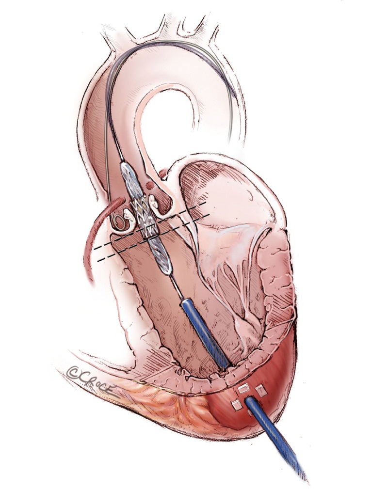
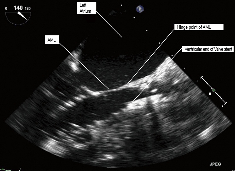
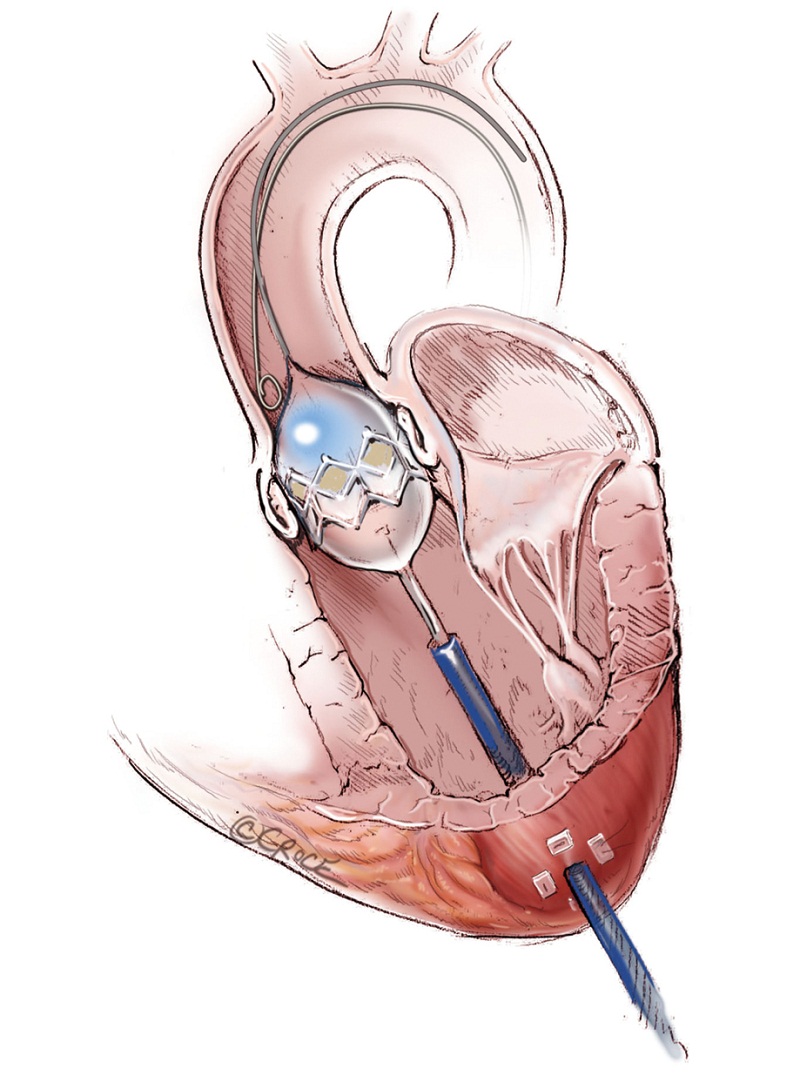
The Edwards SAPIEN balloon expandable transcatheter valve is constructed of trileaflet bovine pericardium on a metal stent. It is crimped onto the delivery balloon. The correct orientation of the transcatheter valve with the Dacron ring at the base of the valve on the ventricular outflow side and open stent on the aortic side must be ensured. After engaging the delivering system, the valve is advanced beyond the tip of the Ascendra sheath under fluoroscopic guidance. Withdrawal of the pusher catheter is then carried out. The SAPIEN valve is positioned within the native AV. The SAPIEN prosthesis is ideally placed 1/3 below the base of aortic sinuses (Figure 9), the bottom of the valve stent positioned ventricularly relative to the line of perpendicularity with the aide of repeat aortic root angiograms. TEE provides additional images that further refine the positioning. Aligning the ventricular end of the valve stent to the aorto-mitral fibrous curtain, the “hinge point’ of the anterior leaflet of the mitral valve, confirms the ideal landing zone (Figure 10). If accurate positioning cannot be achieved due to brisk cardiac motion, rapid pacing with root injections may assist in positioning.
Deployment
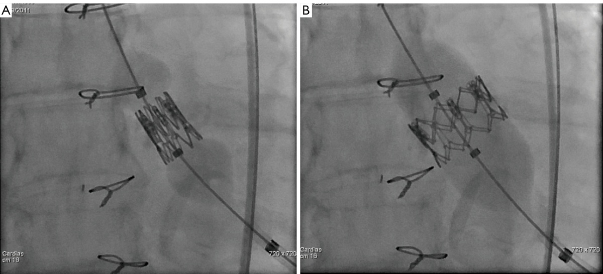
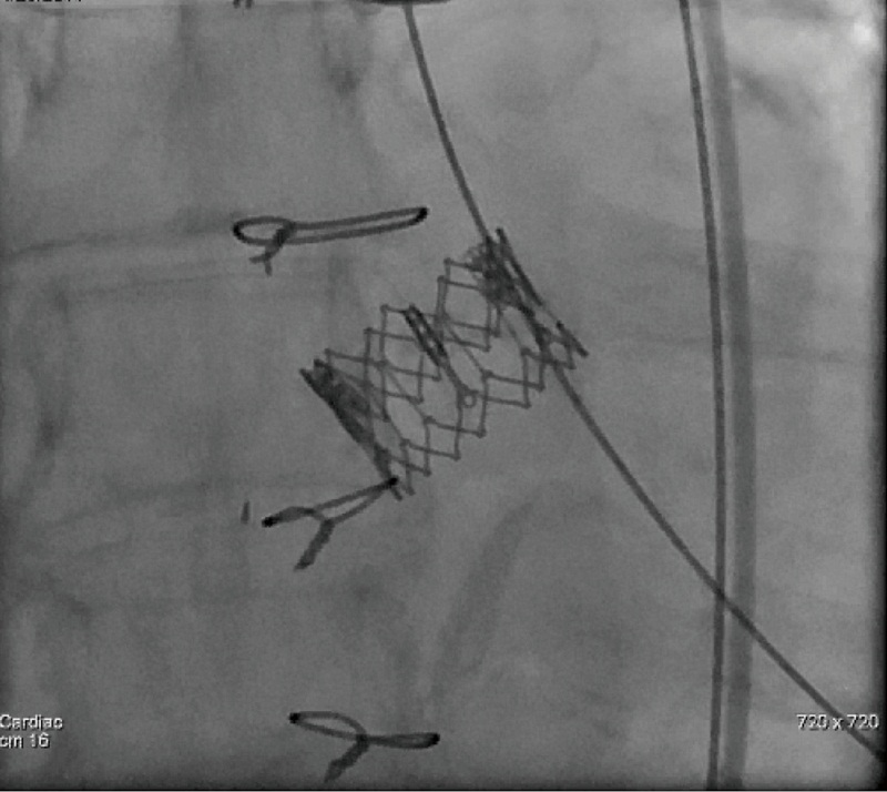
It is extremely important to ensure accurate positioning of the valve prior to its deployment to avoid malpositioing, embolization and significant perivalvular leak. Once acceptable positioning is confirmed using echocardiography and fluoroscopy, the pigtail catheter is withdrawn to the ascending aorta, the pacing protocol is again initiated and the valve is slowly deployed (Figure 11). During deployment, fine adjustment can be made to ensure optimal placement (Figure 12A). Full emptying of the inflation syringe and maintaining full pressure ensures symmetric deployment and prevents stent recoiling (Figure 12B). The balloon is quickly deflated and pacing is ceased. The balloon is pulled back out of the valve stent into the delivery sheath, preventing interference with leaflet function (Figure 13). Once the valve is deployed, echocardiography reports on the stability, location and function of the valve stent, and the degree of perivalvular regurgitation. If valve position is satisfactory and more then moderate degree of perivalvular regurgitation exists, a second attempt with slight higher balloon inflation volume may be attempted. If the degree of central regurgitation through the valve is difficult to evaluate with the Amplatz wire across the valve, it too is withdrawn into sheath. Completion aortogram is seldom perform to minimize the dye load that may adversely effect renal function.
Surgical closure
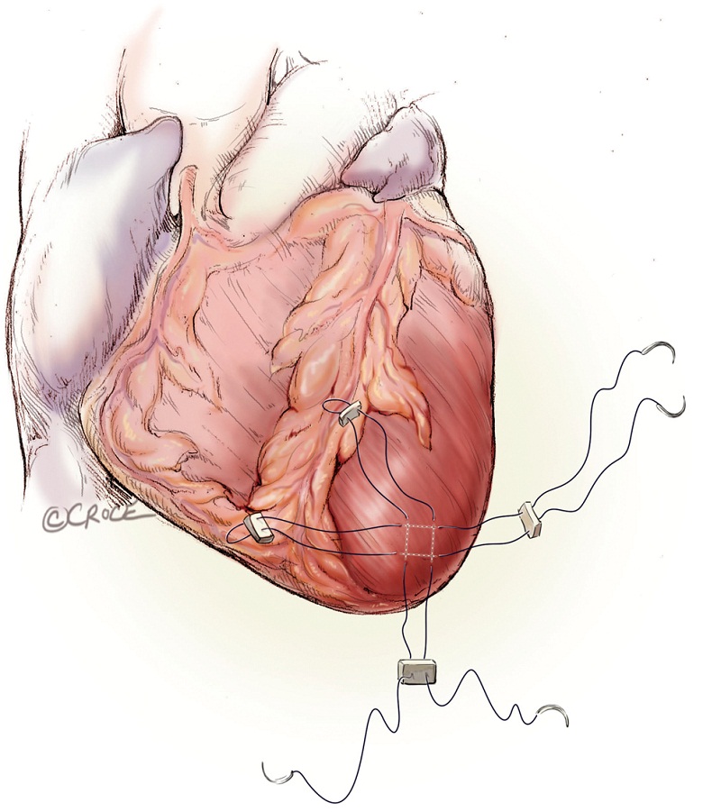
With systolic pressure less than 100 mmHg, the delivery sheath is removed with snugging of the mattress sutures. Then the other orthogonal mattress suture is subsequently tied (Figure 14). Persistent hypertension can be controlled with ventricular pacing at a rate of 100 to 140 bpm. Any blood collections are aspirated from the left chest and local bupivacaine is injected into the intercostal muscles. A small-bore chest drainage tube brought out through a small stab wound is left behind in the left chest. The intercostal muscles are approximated and the skin closed with absorbable subcuticular suture.

Comments
Transcatheter aortic valve replacement is an acceptable treatment option for non-surgical and high-risk surgical candidates. Its clinical application will continue to expand. Transfemoral TAVI is the predominant route of delivery, however, transapical TAVI is a reliable and reproducible procedure in experienced hands.
Acknowledgements
Disclosure: The authors declare no conflict of interest.
References
- Ye J, Cheung A, Lichtenstein SV, et al. Transapical aortic valve implantation in humans. J Thorac Cardiovasc Surg 2006;131:1194-6.
- Lichtenstein SV, Cheung A, Ye J, et al. Transapical transcatheter aortic valve implantation in humans: initial clinical experience. Circulation 2006;114:591-6.
- Walther T, Dewey T, Borger MA, et al. Transapical aortic valve implantation: step by step. Ann Thorac Surg 2009;87:276-83.
- Cheung A, Ree R. Transcatheter aortic valve replacement. Anesthesiol Clin 2008;26:465-79.
- Smith CR, Leon MB, Mack MJ, et al. Transcatheter versus surgical aortic-valve replacement in high-risk patients. N Engl J Med 2011;364:2187-98.
- Mukherjee C, Walther T, Borger MA, et al. Awake transapical aortic valve implantation using thoracic epidural anesthesia. Ann Thorac Surg 2009;88:992-4.

