

Sizing the aortic annulus
Abstract: Transcatheter aortic valve implantation (TAVI) is a valuable alternative for aortic valve replacement in selected high-risk candidates. Accurate preoperative assessment of the aortic annular dimensions is crucial for the success of TAVI, since choice of an incorrectly sized prosthesis may result in catastrophic complications. These complications include annular rupture and coronary arterial obstruction, if the prosthesis is too big, or prosthesis migration and severe paravalvular leakage, if the prosthesis is too small. According to current recommendations, the choice of prosthesis size is based on transoesophageal echocardiography (TEE) measurements. However, TEE results are dependent on operator experience. Moreover, recent research has shown that TEE can significantly underestimate annular dimensional measurements. Alternative sizing methods based on Multidetector Computed Tomography (MDCT) or manometry during balloon aortic valvuloplasty have therefore been developed. We present a brief overview of the imaging modalities available for preoperative assessment of annular size and discuss their potential advantages and limitations.
Key words: Aortic valve replacement; transcatheter aortic valve implantation; balloon aortic valvuloplasty
Introduction
Transcatheter aortic valve implantation (TAVI) is a valuable alternative for aortic valve replacement in selected candidates. To date, TAVI has been performed in more than 20,000 patients worldwide, and data concerning proper indications, optimal techniques and patient outcomes of this procedure continue to accumulate (1). Accurate preoperative assessment of the aortic annulus dimension is crucial for successful TAVI, as an incorrectly sized prosthesis may result in catastrophic complications, whether it is too big, causing annular rupture and coronary arteries obstruction, or too small, resulting in prosthesis migration and severe paravalvular leakage (2). According to the current recommendations, the choice of the prosthesis size is based on transoesophageal echocardiography (TEE) measurements (3). However, TEE results are largely operator dependent. Recent research demonstrates that TEE significantly underestimates the annulus as measured at surgery (4,5). For this reason, alternative sizing methods based on multidetector computed tomography (MDCT) (4,6,7) or manometry during balloon aortic valvuloplasty (BAV) (5,8) have been developed.
Here we present a quick overview of the imaging modalities available for the preoperative assessment of the annular size and discuss their potential advantages and limitations.
Echocardiography
Echocardiography is widely available, reproducible, noninvasive and plays a key role in a patient’s evaluation before and during the TAVI procedure (7). The indications for transcatheter prosthesis size selection provided by the manufacturers are based on transthoracic echocardiography (TTE) and TEE measurements (2,3). Both these techniques may be used to accurately determine the size of the aortic annulus and the excellent results of transcatheter aortic valve replacement reported to date may be attributable to these complementary techniques (1,4,9).
The optimal methods for determining the size of the aortic annulus, the geometry of the left ventricular outflow tract and of the aortic root at echocardiography are well established and the indications for such techniques are widely accepted (2,3,10,11). According to the guidelines of the American Society of Echocardiography, the aortic annulus should be measured as the distance between the insertion of two adjacent leaflets on the parasternal long axis view (TTE) or on the midesophageal long-axis view of the ascending aorta and aortic valve (TEE) at end-systole (Figure 1) (10,11).
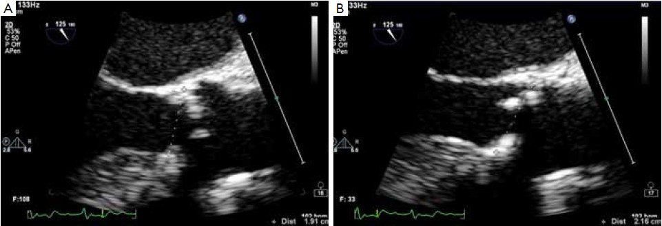
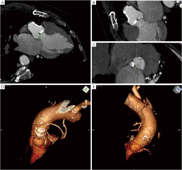
The main limitation of echocardiography relates to its two-dimensional nature. The aortic root in fact has a complex three-dimensional geometry and the semi lunar attachments of the aortic cusps take the shape of a 3-pronged coronet. Working on a uni-planar view leads to the possibility of underestimating or overestimating the annular size, due to the fact that the actual plane of the section may lie out of the annulus center (4,6,12). Threedimensional equipment and a multi-planar reconstruction of the aortic root and of the outflow tract can overcome this limitation but the capacity to visualize the entire annulus can be limited by the calcifications. With bi-dimensional equipment the section of the annulus can be maximized by choosing the largest measure of the annulus, taking care to obtain a symmetrical visualization of the cusps. In this case the section plane is supposed to pass through the nadir of two cusps close to the center of the outflow tract (Figure 1). However, irrespective of the imaging modality employed, “hinge to hinge” measurements on bi-planar images are often inaccurate. For instance, measuring the distance between the basal attachment of one leaflet to the depicted hinge point across the lumen will take a more diagonal path in relation to the aortic root’s axis, while a measurement between the basal attachments of two adjacent leaflets would represent a secant across the aortic root, resulting in a overestimation or underestimation of the annular size respectively (Figure 2) (6,12). Moreover, recent research has shown that the hinge points of the three aortic valve cusps is the tissue that provides the first resistance and anchoring force to the transcatheter valve stent. These points lie on the so-called “Virtual basal ring” (12,13), which represents the transition between the left ventricular outflow tract and the aortic root. The virtual basal ring is elliptical and largely non-homogeneous, adding further complexity to any attempt to measure the aortic annulus diameter on two-dimensional images (6,7,9,14). These concepts have been illustrated well by Piazza and associates in a recent review (12).
Multidetector computed tomography
Beyond diameter measurements, a detailed understanding of the anatomy is essential in predicting the final shape of the prosthetic valve, displacement of the native calcified leaflets and sealing around the prosthesis (9). Multidetector computed tomography (MDCT) allows a detailed understanding of the complex three-dimensional aortic root anatomy, including the crown-shaped anatomic aortic annulus, the virtual basal ring, the sinuses of Valsalva with the origin of the coronary arteries, the valve leaflets and the sinotubular junction. MDCT has become the “gold standard” for non-invasive preoperative evaluation of the aortic root and aortic annulus prior to TAVI (4,6,7,12,13,15-20).
Several scan protocols for TAVI assessment have been developed. The technical details on how to obtain a good scan are beyond the scope of this article, but a high quality acquisition without artifacts is a pre-requisite for all the post-processing and image analysis (20).
Many different techniques have been developed to measure the aortic annular diameter at MDCT (6,7,20). In general, they can be divided into two main categories: hingeto- hinge measurements on a single oblique view (similar to what it is done at echocardiography) (Figure 3) (6,16,19); and measurements derived from the area or the circumference of the virtual basal ring (Figure 4) (4,6,18,20,21). In this second case, the virtual basal ring may be traced manually or automatically assessed by dedicated post-processing software (21).
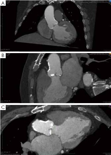
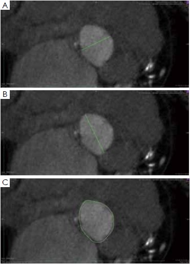
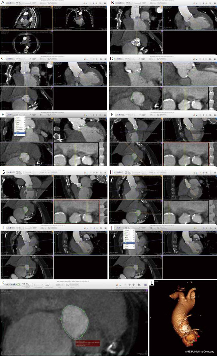
To manually trace the virtual basal ring, the three multi-planar reformation planes are used. The orientation of the horizontal line representing the axial cut-plane across the aortic root is adjusted on the sagittal and coronal planes to obtain a double oblique transverse view at the level of the aortic root. The line is then moved from the aorta to the ventricle until the most caudal attachment of the three aortic cusps is identified. Ideally, when the orientation of the cut-plane is appropriate, all the three leaflets should disappear and appear at the same time while scrolling the horizontal line caudally or cephalad across the virtual basal ring respectively (Figure 4, Figure 5A, B, C). It should be observed, however, that the exact identification of the plane on which the basal ring lays is not always straightforward in clinical practice. In fact, the nadir of any particular cusp is located at the point where that cusp is “seen to disappear,” and the operator judges that the plane is correctly oriented when the three cusps disappear all together, an occurrence that may be hard to reproduce in some patients, such as those with heavy or asymmetrical annular calcifications or an extremely elliptical annulus. While it is easy to identify the “height” of the nadir of a cusp in the aortic root on the sagittal and coronal oblique views, its angular position on the annular circumference may be hard to locate in some patients. An easy, step-by-step method to overcome this issue is described in Figure 5.
A large amount of evidence has accumulated demonstrating that the MDCT measurements based on the calculation of the average diameter of the virtual basal ring from the virtual basal ring area or circumference are much more accurate and reproducible than echocardiography, and that the use of the MDCT derived measures would result in a strategy change in a substantial number of patients (4,6,15-18,22). Furthermore, it has recently been demonstrated that transcatheter valve implantation alters the geometry of the aortic annulus to a more circular configuration. Interestingly, there is a close and significant correlation between the pre-implant area of the elliptical virtual basal ring and the area of the circularized, post-implant aortic annulus, meaning that MDCT could help to predict the final shape and dimension of the aortic annulus-prosthesis complex after the valve implantation (6). Finally, recent evidence suggests that the use of MDCT for annulus sizing and prosthesis size selection could result in a significant reduction in the risk of post-procedural paravalvular aortic regurgitation, a complication that is known to negatively affect the short- and mid- term results of TAVI (6,15,17,18,22).
Assessment of the annulus diameter by calibrated balloon aortic valvuloplasty:more than just a number
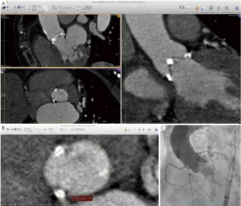
As suggested, MDCT may become the gold standard for non-invasive assessment of the aortic annulus, since it allows a detailed evaluation of aortic root anatomy, and can predict the final shape and orientation of the transcatheter valve and of the aortic root after valve deployment. Despite these advances, complications of TAVI are still reported in the MDCT era, even with experienced TAVI operators. (Figure 6) (15-20,22).
For obvious reasons, calibrated aortic angiography has been among the first techniques used to measure the aortic annulus. Balloon inflation with simultaneous contrast injection to check the “stop flow” diameter was originally described by Alain Cribier (23), and it is still an excellent method to determine the size of the transcatheter prosthesis to be implanted (14). In fact, the behavior of the aortic root and aortic annulus during the deployment of transcatheter valves is not always predictable based only on the preoperative non-invasive imaging (9). This is partly due to intrinsic anatomic properties of the aortic root - the “virtual ring” is largely non-homogeneous, coursing through the muscular septum, the membranous septum and the mitralaortic curtain. Moreover, leaflet and annular calcifications are often asymmetrical, adding further complexity to any attempt to predict the final shape of the prosthetic valve, the displacement of the native calcified leaflets and the sealing of the annulus around the prosthesis. Appropriate device sizing may therefore be dependent on the observation of anatomy–device interaction and aortic angiography during calibrated balloon valvuloplasty represents a very simple and safe method to test this interaction prior to valve deployment (5,8,14,23).
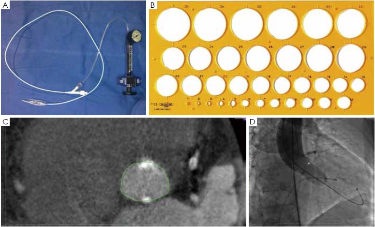
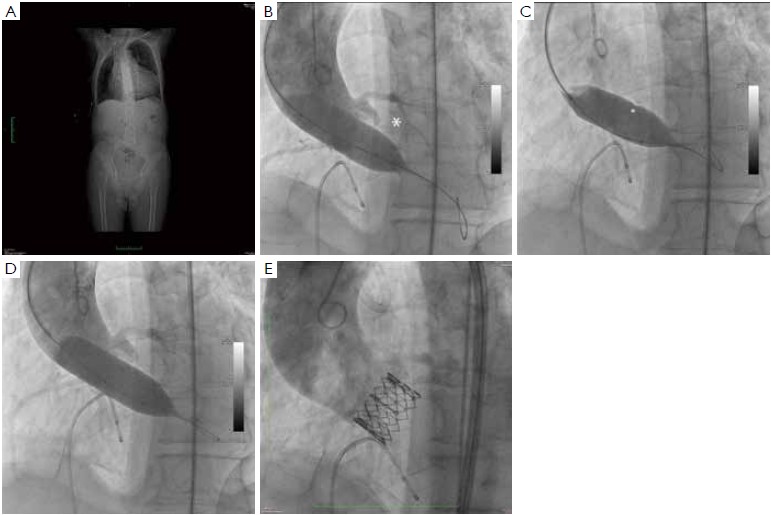
At our institution, the indications for invasive assessment of the aortic annulus size by calibrated balloon aortic valvuloplasty are as follows: (I) major discrepancy between the results of the non-invasive measures; (II) borderline annulus (21-22 and 24-25 mm); (III) massive and/or eccentric calcifications of the aortic annulus/leaflets; (IV) bicuspid aortic valve. The procedure is performed in the catheterization laboratory, as part of the implant procedure (for percutaneous procedures) or during preoperative cardiac catheterization (for transapical procedures). An appropriately sized valvuloplasty balloon (Cristal Balloon, Balt, Montmorency, France) is inflated on the bench with a known volume of diluted contrast agent (15% iomeprol), and is then sized with a sterile plastic mask for technical drawing (Figure 7A, B). The initial volume of inflation is set to obtain a balloon size of 1 mm less than the TEE measurement. The balloon is positioned across the aortic valve through a 10 gauge femoral sheath and inflated with the same volume during rapid ventricular pacing, using a manometric deflator device connected to a 30 cc inflation syringe. At full inflation, an aortography is performed. The following parameters are recorded: (I) presence of a waist on the balloon at the level of the annulus, (II) intra-balloon pressure, (III) patency of the coronary artery ostia and their relations with the displaced aortic valve cusps, (IV) presence and entity of aortic regurgitation on aortography at full balloon inflation (“para-balloon leak”) (Figure 7). In the absence of a waist on the balloon and/or in case of major para-balloon leak, the procedure is repeated with a larger diameter balloon (larger balloon or same balloon inflated with a larger volume of contrast media) (Figure 8).
From January 2009 to December 2011, 31 patients at our institution underwent balloon aortic valvuloplasty for annulus size determination as part of the evaluation process prior to TAVI. The procedure was motivated primarily by an incomplete or dubious characterization of aortic root anatomy by non-invasive techniques. Interestingly, this approach led to a strategy change (selection of a different size prosthesis or switch to conventional surgery) in 7 patients (22.6%). Of note, there were no cases of annulus or aortic rupture, aortic dissection, coronary ostia occlusion, prosthesis migration or more than mild paraprosthetic leak in this series.
Babaliaros and coworkers described a similar pressurebased technique to size the aortic annulus during balloon aortic valvuloplasty (5,8). A balloon of known diameter was inflated on the bench and its internal pressure was recorded. The balloon was then positioned across the aortic valve and inflated. The development of additional intra-balloon pressure was considered proof of the fact that the aortic annulus had been stretched and the nominal diameter of the balloon was used to size the annulus and choice the appropriate size prosthesis (8). In our experience, the development of additional intra-balloon pressure was not always associated with a complete circularization of the annulus and sealing of the balloon to the ventriculo-aortic junction. Indeed we used the intra-balloon pressure as a safety measure, taking care not to exceed the 4 atmospheres limit indicated by the manufacturer of the balloon during the inflation. Instead, we considered the absence of paraballoon leakage during aortography as the true end point of the procedure. In some patients, the additional intraballoon pressure was developed along with a waist on the balloon profile when the aortography still showed and important para-balloon leakage and inflating the balloon with a slightly larger volume resulted in disappearance of the waist and of the leakage. Interestingly, however, the results of Babaliaros were similar to ours and in 25% of their patients balloon sizing resulted in selection of a transcatheter valve size that could not be achieved by TEE alone (8). This would confirm the idea that the preoperative non-invasive assessment of the aortic annulus may be not sufficiently accurate for some patients (9,14).
Conclusions
All the available imaging modalities provide important information on the anatomy of the aortic root and should be used in a complementary fashion to achieve optimal results. Due to its ability to generate three-dimensional isotropic images, MDCT should be considered the gold standard for the assessment of the average aortic annulus diameter on the virtual basal ring and for the evaluation of the relationship between the annulus, the aortic leaflets and the coronary ostia. Alternatively, echocardiography is readily available, does not require the use of contrast media and may be used during the valve implantation to monitor the procedure. Balloon aortic valvuloplasty is a safe and effective means of obtaining a direct measurement of the aortic annulus prior to TAVI and the information that it provides may significantly alter the prosthesis size selection process, helping to optimize the therapeutic strategy in selected patients. Furthermore, this technique may provide additional information that is crucial for the success of TAVI, simulating the behavior of the aortic annulus, of the valve leaflets and of the coronary artery ostia during the deployment of balloon expandable transcatheter valves, and allowing to “feel” the aortic annulus while measuring it.
Acknowledgements
Disclosure: The authors declare no conflict of interest.
References
- Ruel M, Dickie S, Chow BJ, et al. Interventional valve surgery: building a team and working together. Semin Thorac Cardiovasc Surg 2010;22:145-9.
- Delgado V, Tops LF, Van der Kley F, et al. Imaging-How can it help before transcatheter aortic valve implantation? In: Serruys PW, Piazza N, Cribier A, et al. editors. Transcatheter aortic valve implantation. Tips and tricks to avoid failure. New York: NY, Informa Healtcare USA, Inc 2010:40-56.
- Vahanian A, Alfieri O, Al-Attar N, et al. Transcatheter valve implantation for patients with aortic stenosis: a position statement from the European Association of Cardio-Thoracic Surgery (EACTS) and the European Society of Cardiology (ESC), in collaboration with the European Association of Percutaneous Cardiovascular Interventions (EAPCI). Eur Heart J 2008;29:1463-70.
- Dashkevich A, Blanke P, Siepe M, et al. Beyersdorf F. Preoperative assessment of aortic annulus dimensions: comparison of noninvasive and intraoperative measurement. Ann Thorac Surg 2011;91:709-14.
- Babaliaros VC, Liff D, Chen EP et al. Can balloon aortic valvuloplasty help determine appropriate transcatheter aortic valve size? JACC Cardiovasc Interv 2008;1:580-6.
- Blanke P, Siepe M, Reinöhl J, et al. Assessment of aortic annulus dimensions for Edwards SAPIEN Transapical Heart Valve implantation by computed tomography: calculating average diameter using a virtual ring method. Eur J Cardiothorac Surg 2010;38:750-8.
- Messika-Zeitoun D, Serfaty JM, Serfaty JM, et al. Multimodal assessment of the aortic annulus diameter: implications for transcatheter aortic valve implantation. J Am Coll Cardiol 2010;55:186-94.
- Babaliaros VC, Junagadhwalla Z, Lerakis S, et al. Use of balloon aortic valvuloplasty to size the aortic annulus before implantation of a balloon-expandable transcatheter heart valve. JACC Cardiovasc Interv 2010;3:114-8.
- Tuzcu EM, Kapadia SR, Schoenhagen P. Multimodality quantitative imaging of aortic root for transcatheter aortic valve implantation. More complex than it appears. J Am Coll Cardiol 2010;55:195-7.
- Lang RM, Bierig M, Devereux RB, et al. Recommendations for chamber quantification: a report from the American Society of Echocardiography’s Guidelines and Standards Committee and the Chamber Quantification Writing Group, developed in conjunction with the European Association of Echocardiography, a branch of the European Society of Cardiology. J Am Soc Echocardiogr 2005;18:1440-63.
- Shanewise JS, Cheung AT, Aronson S, et al. ASE/SCA guidelines for performing a comprehensive intraoperative multiplane transesophageal echocardiography examination: recommendations of the American Society of Echocardiography Council for Intraoperative Echocardiography and the Society of Cardiovascular Anesthesiologists Task Force for Certification in Perioperative Transesophageal Echocardiography. J Am Soc Echocardiogr 1999;12:884-900.
- Piazza N, de Jaegere P, Schultz C, et al. Anatomy of the aortic valvar complex and its implications for transcatheter implantation of the aortic valve. Circ Cardiovasc Interv 2008;1:74-81.
- Tops LF, Wood DA, Delgado V, et al. Noninvasive evaluation of the aortic root with multislice computed tomography implications for transcatheter aortic valve replacement. JACC Cardiovasc Imaging 2008;1:321-30.
- Cerillo AG, Mariani M, Glauber M, et al. Sizing the annulus for transcatheter aortic valve implantation: more than a simple measure? Eur J Cardiothorac Surg 2012;41:717-8.
- Kempfert J, Van Linden A, Lehmkuhl L, et al. Aortic annulus sizing: echocardiographic vs. computed tomography derived measurements in comparison with direct surgical sizing. Eur J Cardiothorac Surg 2012. [Epub ahead of print].
- Gurvitch R, Webb JG, Yuan R, et al. Aortic annulus diameter determination by multidetector computed tomography: reproducibility, applicability, and implications for transcatheter aortic valve implantation. JACC Cardiovasc Interv 2011;4:1235-45.
- Willson AB, Webb JG, Labounty TM, et al. 3-dimensional aortic annular assessment by multidetector computed tomography predicts moderate or severe paravalvular regurgitation after transcatheter aortic valve replacement: a multicenter retrospective analysis. J Am Coll Cardiol 2012;591287-94.
- Schultz CJ, Moelker A, Piazza N,et al. Three dimensional evaluation of the aortic annulus using multislice computer tomography: are manufacturer’s guidelines for sizing for percutaneous aortic valve replacement helpful? Eur Heart J 2010;31:849-56.
- Wood DA, Tops LF, Mayo JR, et al. Role of multislice computed tomography in transcatheter aortic valve replacement. Am J Cardiol 2009;103:1295-301.
- Leipsic J, Gurvitch R, Labounty TM, et al. Multidetector computed tomography in transcatheter aortic valve implantation. JACC Cardiovasc Imaging 2011;4:416-29.
- Delgado V, Ng AC, Schuijf JD, et al. Automated assessment of the aortic root dimensions with multidetector row computed tomography. Ann Thorac Surg 2011;91:716-23.
- Jilaihawi H, Kashif M, Fontana G, et al. Cross-sectional computed tomographic assessment improves accuracy of aortic annular sizing for transcatheter aortic valve replacement and reduces the incidence of paravalvular aortic regurgitation. J Am Coll Cardiol 2012;59:1275-86.
- Cribier A, Eltchaninoff H. Preimplantation percutaneous aortic balloon valvotomy - Aortogram during balloon inflation: technique and interest. In: Serruys PW, Piazza N, Cribier A, Webb JG, Laborde J, de Jaegere P, editors. Transcatheter aortic valve implantation. Tips and tricks to avoid failure. New York, NY, Informa Healtcare USA, Inc 2010:167-8.

